
Are you an electronics enthusiast or a hobbyist looking to dive into the world of Arduino Uno? If so, understanding the pinout and capabilities of this popular microcontroller board is crucial. The Arduino Uno is a versatile and powerful board, perfect for a wide range of projects, from simple LED blinking to complex robotics.
In this article, we will take an in-depth look at the Arduino Uno pinout and explore various aspects of its functionality. We’ll cover essential topics like power supply, analog and digital pins, and key communication protocols such as PWM, serial communication, SPI, and I2C. Additionally, we’ll delve into the significance of ICSP headers and how they can enhance your Arduino Uno experience.
So, let’s embark on this enlightening journey and uncover the secrets of Arduino Uno pins!
Arduino Uno Pinout – Power Supply:
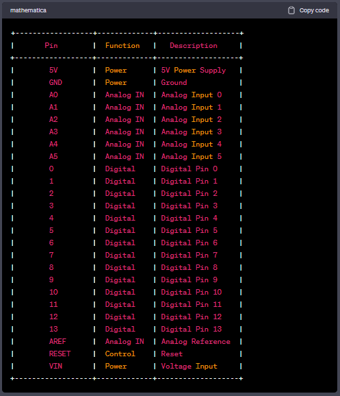
Powering your Arduino Uno correctly is fundamental to ensure its stable operation. The board offers multiple options for power input, providing flexibility to meet various project requirements. The primary power supply methods are:
- USB: The Arduino Uno features a USB connector, allowing you to power it directly from your computer or any USB power source. This method is convenient for prototyping and programming scenarios;
- Barrel Jack: The barrel jack input is another popular power supply option. It accepts a 9V to 12V DC power adapter, enabling you to connect the Arduino Uno to a wall outlet or a dedicated power source. This method is ideal when you need a standalone operation or more power for your project;
- Vin Pin: In addition to the USB and barrel jack, the Arduino Uno provides a Vin pin. By supplying a regulated voltage between 7V and 12V directly to this pin, you can power the board effectively.
Remember to consider the power requirements of your project and choose the most suitable power supply method accordingly. It’s vital to avoid overpowering or underpowering your Arduino Uno, as it can lead to erratic behavior or even damage the board.
Arduino Uno Pinout – Analog IN:
One of the key features that sets the Arduino Uno apart is its analog input capability. Analog inputs allow the board to interface with the physical world, enabling you to measure and respond to real-world variables such as light, temperature, pressure, and more. The Arduino Uno offers six analog input pins, labeled A0 through A5, each capable of measuring voltages within a range of 0 to 5 volts.
To use the analog input pins effectively, you need to understand how to read analog values and convert them into meaningful data. The Arduino programming language provides the analogRead() function, which allows you to read the analog voltage values from these pins. The function converts the analog voltage into a digital value ranging from 0 to 1023, representing the 0 to 5-volt range.
It’s important to note that the Arduino Uno utilizes a 10-bit analog-to-digital converter (ADC), meaning it can represent the analog voltage with a resolution of 1024 steps. This level of precision allows for accurate measurements and fine-grained control over analog signals.
When using the analog input pins, consider the voltage range of the sensors or signals you are working with. The Arduino Uno operates with a 5-volt reference voltage, so ensure that your sensor’s output voltage falls within this range. If you are working with sensors that operate at different voltage levels, you may need to use voltage dividers or amplifiers to scale the voltage appropriately.
Additionally, it’s worth mentioning that the analog input pins can also be used as digital input or output pins if the need arises. This flexibility adds to the versatility of the Arduino Uno, allowing you to adapt to different project requirements.
When working with analog inputs, it’s important to keep in mind that analog signals are susceptible to noise and interference. To minimize these issues, you can employ techniques like signal filtering and shielding. Signal filtering involves using capacitors or low-pass filters to remove high-frequency noise, while shielding involves enclosing sensitive components in a grounded enclosure to block external interference.
By harnessing the power of the Arduino Uno’s analog input pins, you can create projects that interact with and respond to the analog world around you. Whether you’re building a weather station, a light-sensitive alarm, or a temperature-controlled system, the analog inputs of the Arduino Uno offer endless possibilities for capturing and processing real-world data. Experiment with different sensors, explore signal conditioning techniques, and let your creativity take flight as you unlock the potential of analog inputs in your Arduino Uno projects.
Arduino Uno Pinout – Digital Pins:
The Arduino Uno offers a total of 14 digital input/output pins, marked as D0 to D13. These pins can be used for both digital input and output operations, allowing you to interface with various components such as buttons, LEDs, and relays. Each of these pins can operate in either of the two modes:
- Input Mode: In this mode, the pin can read a digital value, detecting whether it is high (1) or low (0). You can use digitalRead() function to read the state of the pins;
- Output Mode: In this mode, the pin can provide a digital output of either high (1) or low (0). You can use digitalWrite() function to set the state of the pins.
The digital pins on the Arduino Uno are also capable of Pulse Width Modulation (PWM). Let’s explore this concept in more detail.
What does digital mean? What is PWM?
In the world of electronics, digital refers to signals or systems that have only two discrete states: high (1) or low (0). These two states represent the presence or absence of an electrical signal, allowing for straightforward and reliable communication and control.
Digital signals are the foundation of modern electronics and computing. They form the basis of binary code, the language that computers use to process and store information. The binary system’s simplicity and robustness make it ideal for transmitting and manipulating data with high accuracy and noise immunity.
The Arduino Uno, like many microcontrollers, operates primarily in the digital realm. Its digital pins can be configured as inputs or outputs, enabling communication with various external devices and components.
Now, let’s dive into an essential concept related to digital signals: Pulse Width Modulation (PWM). PWM is a technique used by the Arduino Uno and other microcontrollers to simulate analog output using digital pins.
An analog signal is continuous and can have any value within a range, while a digital signal is discrete and can only be high or low. PWM bridges the gap between digital and analog by varying the width of a pulse while keeping the frequency constant. By rapidly switching a digital pin between high and low states, you can achieve an average voltage level, effectively generating an analog-like signal.
The key idea behind PWM is that the human eye or other analog systems perceive rapid on-off switching as a varying voltage or intensity. For example, imagine you want to control the brightness of an LED. Instead of supplying a continuous voltage, you can use PWM to control the LED’s average brightness by adjusting the width of the pulses. A wider pulse results in a higher average voltage and a brighter LED, while a narrower pulse decreases the average voltage and dims the LED.
The Arduino Uno offers PWM capabilities on certain digital pins, allowing you to control the intensity of LEDs, the speed of motors, and the position of servos. The analogWrite() function in the Arduino programming language is used to generate PWM signals. You can specify a value between 0 and 255, representing the duty cycle of the PWM signal. A duty cycle of 0 results in a signal that is always off (0 volts), while a duty cycle of 255 gives a signal that is always on (5 volts for the Arduino Uno operating at 5V). Intermediate values produce varying average voltages, allowing for precise control over connected devices.
PWM is widely used in applications where fine-grained control over analog-like behavior is required, but only digital signals are available. It finds applications in robotics, motor control, lighting systems, and audio amplification, to name just a few examples.
By harnessing the power of PWM, the Arduino Uno opens up a world of possibilities for creating dynamic, responsive, and interactive projects. Experiment with different duty cycles, explore PWM-driven components, and unleash your creativity as you master the art of simulating analog signals in the digital domain.
What is Serial Communication? What is SPI? What is I2C?
Serial communication, SPI (Serial Peripheral Interface), and I2C (Inter-Integrated Circuit) are vital communication protocols that enable data transfer between the Arduino Uno and other devices.
- Serial Communication: Serial communication involves the transmission of data sequentially, one bit at a time, over a single wire. The Arduino Uno has a dedicated hardware serial interface, which allows you to establish communication with other devices, such as computers, sensors, and modules, using the Universal Asynchronous Receiver-Transmitter (UART) protocol;
- SPI (Serial Peripheral Interface): SPI is a synchronous serial communication protocol that enables high-speed data transfer between microcontrollers and peripheral devices. The Arduino Uno has dedicated pins (MISO, MOSI, SCK, and SS) for implementing SPI communication, making it compatible with a wide range of SPI-enabled sensors, displays, and other components;
- I2C (Inter-Integrated Circuit): I2C is a popular two-wire communication protocol that enables multiple devices to communicate with each other using a shared bus. The Arduino Uno has dedicated pins (SDA and SCL) for I2C communication, allowing you to connect and interact with a plethora of I2C devices, including sensors, LCD displays, and EEPROMs.
These communication protocols expand the capabilities of the Arduino Uno, facilitating seamless integration with various external devices and expanding the possibilities for your projects.
Arduino Uno Pinout – ICSP Header:
The ICSP (In-Circuit Serial Programming) header on the Arduino Uno board provides an alternative programming interface that allows you to program the ATmega328P microcontroller directly. This header exposes important pins such as MISO, MOSI, SCK, RESET, 5V, and GND, which are necessary for programming and advanced hardware interaction.
The ICSP header serves as a gateway to advanced programming techniques and capabilities, going beyond the standard USB-based programming provided by the Arduino IDE. It allows you to use external programmers, such as AVR ISP (In-System Programmer) or USBASP (USB Asp Programmer), to directly write firmware to the microcontroller.
One significant advantage of utilizing the ICSP header is the ability to bypass the USB connection. This can be useful in scenarios where you want to program the Arduino Uno without being connected to a computer. You can power the board through an external power source and use the ICSP header to upload your code directly. This feature makes the Arduino Uno more portable and enables standalone operation in various projects.
In addition to programming, the ICSP header also opens up possibilities for advanced hardware interactions. For instance, it allows you to interface with external devices that communicate using protocols such as SPI (Serial Peripheral Interface) or ICSP itself. By connecting compatible devices to the appropriate pins on the ICSP header, you can expand the capabilities of your Arduino Uno.
Furthermore, the ICSP header can be utilized for burning bootloaders onto the Arduino Uno. A bootloader is a small program that resides in the microcontroller’s memory and enables easy firmware updates. With the ICSP header, you can replace or update the bootloader if needed, providing flexibility and customization options for your Arduino Uno projects.
It’s important to note that when using the ICSP header, you need to ensure proper pin connections and follow the specific programming instructions for your chosen external programmer. The Arduino IDE provides support for programming the Arduino Uno through the ICSP header, allowing you to select the appropriate programmer and specify the programming parameters.
In summary, the ICSP header on the Arduino Uno offers an alternative programming interface and advanced hardware interaction capabilities. It enables you to program the microcontroller directly, bypassing the USB connection, and provides opportunities for using external programmers, interfacing with SPI devices, and burning bootloaders. By leveraging the ICSP header, you can take your Arduino Uno projects to the next level of customization and control, expanding the possibilities of what you can achieve with this versatile microcontroller board.
Conclusion:
Understanding the pinout and capabilities of the Arduino Uno is essential for unleashing its full potential in your projects. In this comprehensive guide, we have explored the power supply options, analog and digital pins, communication protocols, and the significance of the ICSP header.
Remember to choose the appropriate power supply method based on your project’s requirements to ensure stable operation. Take advantage of the analog input pins to interface with analog sensors accurately. Explore the digital pins’ versatility and leverage PWM for precise control over various components. Familiarize yourself with serial communication, SPI, and I2C protocols to establish seamless connections with external devices. Lastly, experiment with the ICSP header to delve deeper into the capabilities of your Arduino Uno.
Now armed with this knowledge, you can embark on exciting Arduino Uno projects and bring your creative ideas to life!